… according to the experts, and continue through its active life. All along, operators should consider what they will need to show regulators once they are ready to install the final cap.
Choosing the right designer for liquids and gas management is critical. The complexity of landfills varies from site to site, and issues related to conflicts among gas and liquids pipes, and pipes and final cover geosynthetics vary depending on the geometry and other landfill features involved at each location. In short, your designers must understand and work closely with your operations and monitoring team.
The best way to resolve conflicts before the closure is to have a coordinated effort among parties involved in the design to discuss and find solutions to every conflict at the design stage.
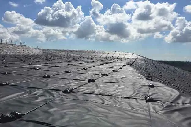
Landfill slopes that have reached final grades, or will receive waste in the distant future have maintenance challenges. Environmental elements continually affect surface conditions, and remedial work is required routinely to prevent negative outcomes of exposed slopes. Consider using a geomembrane temporary cap to address much of the maintenance. Here’s a list showing how the cap can help:
Landfill Maintenance Challenge
Washouts due to stormwater runoff
Need to establish a vegetative cover
Maintain grass regularly
Leachate seeps appearing without warning
Landfill odors after storms
Surface disturbance from gas lines or associated construction
Leachate generation from rainwater percolation
With Geomembrane Temporary Cap
No washouts – sheet flow of stormwater runoff over the geomembrane
No need for a vegetative cover
No mowing, or cutting paths to read a well
Leachate seeps diminish with a temporary impermeable layer
Additional barrier to control landfill odors
Easily place gas lines above the geomembrane
Less percolation equates to less leachate generation from the capped area
The significant maintenance savings by using a temporary cap make the payoff period for the investment attractive. Based on my experience and site variations, the return on investment is usually three to six years. The period is considerably shorter if your landfill does not have a leachate disposal or treatment system, or deep injection well. The difference is the high cost to have the leachate hauled away.
Temporary caps potentially reduce routine maintenance work, leaving operation staff available for other tasks. The cap provides peace of mind that slopes remain in compliance; regulators don’t need to report non-compliance conditions of exposed slopes during inspection events.
After completing 25 temporary cap projects in the U.S. Southeast alone, we highly recommend using a thick geomembrane. It’s tempting to try to save money using a thinner geomembrane, such as 12 mils or 20 mils, but these can damage more easily and will negatively affect your return. The majority of SCS clients chose to use the recommended 40 mils thick geomembrane, which will survive severe weather conditions.
Ballasting the geomembrane and using the right materials for ballasting is significantly important. We recommend using ultraviolet (UV) resistant rope and sandbags, a tried and true system. UV resistant straps are a decent replacement for ropes. Anchoring mechanisms are also important. We typically recommend using 4×4 treated wood posts at 10-ft spacing, installed in anchor trenches, and tied to ballasting ropes. Depending on the site and operator’s preference, the supporting architecture may be to lay the post horizontally, while tied to the ballasting ropes, at the bottom of the anchor trench buried in the anchor trench’s backfill material.
Over the years, landfill operators have experienced the savings and value that temporary caps bring to landfill operating budgets, and we’re placing more temporary caps every year. If considering this option, SCS can assist you by evaluating the slopes at your site for the caps. We’ll also prepare estimates for the purchase of material and installation costs and estimated time of recovery for your project.
About the Author: Ali Khatami, Ph.D., PE, LEP, CGC, is a Project Director and a Vice President of SCS Engineers. He is also our National Expert for Elevated Temperature Landfills, plus Landfill Design and Construction Quality Assurance. He has nearly 40 years of research and professional experience in mechanical, structural, and civil engineering.
Landfills, especially large regional landfills, are huge enterprises with many different operations ongoing daily. A landfill’s tangible assets are equipment, buildings, machinery, construction materials in the ground, or stockpiled to support various operations. Of all these, the most significant asset is the permitted airspace. It’s undoubtedly a non-tangible asset when permitted, but gradually this asset gets consumed as it turns into revenue.
Creating landfill airspace during a design/permitting process involves the operator hiring a landfill engineer to develop the concept of the airspace, prepare an appropriate design with engineering methods, and obtain a permit for it through regulatory agencies. In a sense, a portion of your future revenue is in the hands of your landfill engineer. You depend on this engineer to create the maximum amount of airspace, generating the maximum amount of revenue for your operation over time. Your engineer is supposed to be your trusted partner, and you are investing an enormous amount of capital for the design, permit, and construction based on the work performed by the engineer.
In some instances, the operator leaves most of the technical decision making to the engineer. On other occasions, the operator is in the loop during the engineer’s design, but the operator is not heavily involved in the nuances of the disposal cell’s layout in consideration of the existing terrain. In either case, the engineer is significantly responsible for achieving the maximum amount of airspace. The multi-million dollar question is whether you could have had another 3 million or 5 million cubic yards of additional airspace in your permit. How do you check if your landfill engineer maximized airspace in the design?
Assuming proper training, most landfill engineers can design adequate landfills. Still, very few landfill engineers have the unique talent and experience that can maximize airspace within specific design parameters. You, as the operator want engineers with a proven track record of maximizing airspace in their landfill designs, and do not let relationships or political nuances affect your judgment during selection because tens of millions of dollars of additional revenue are at stake.
A trained landfill engineer may miss details that a highly qualified engineer would not. Incidentals here and there, if recognized and accounted for, can add significant airspace to the design. These details vary from site to site, and it’s up to the engineer to recognize the benefits of geometric and regulatory opportunities to add to the covered airspace. These details could be in the form of:
Special geometries for the landfill slopes,
The lateral extent of waste limits,
The landfill footprint placement within the terrain,
The extent of excavation for establishing bottom grades for disposal cells,
The relative position of base grades with respect to the groundwater elevations,
Combining leachate collection sumps among two or more disposal cells,
Steeper slopes to increase airspace while staying within the bounds of regulatory requirements,
Positioning peripheral systems in a different way to benefit from additional land to add to the landfill footprint,
Considering future expansion down the road and planning appropriately, and
Other nuances that an expert considers.
The operator chooses the project manager or the primary engineer for the design of a greenfield landfill or an expansion to an existing landfill, knowing that the work performed by the selected engineer could potentially add to or take away hundreds of millions of dollars from the bottom line of your enterprise. So, pick your engineer based on the engineer’s prior design track record and make sure the engineer is an expert in maximizing landfill airspace.
SCS is an expert, highly experienced landfill designer – relied on by many landfill operators as a trusted partner. Our culture is to serve our clients as if their project is our own, and we do not consider ourselves successful unless our clients are satisfied. These close relationships help us serve the majority of our clients on a long-term basis, with decades of continuous service and value.
SCS will gladly evaluate scenarios for your landfill expansions that you are planning to design and permit, and provide you with a preliminary estimate of airspace gain and revenue that an SCS design could bring, potentially increasing your primary asset by another tens of millions of dollars. Now that’s a value statement!
About the Author: Ali Khatami, Ph.D., PE, LEP, CGC, is a Project Director and a Vice President of SCS Engineers. He is also our National Expert for Landfill Design and Construction Quality Assurance. He has nearly 40 years of research and professional experience in mechanical, structural, and civil engineering.
The industry is designing and building more substantive drainage features and larger collection systems from the bottom up, that maintain their integrity and increase performance over time, thus avoiding more costly problems in the future.
Waste360 spoke with three environmental engineers about what landfill operators should know about liquids’ behavior and what emerging design concepts help facilitate flow and circumvent problems such as elevated temperature landfills, seeps, and keep gas flowing.
The engineers cover adopting best practices and emerging design concepts to facilitate flow. They cover topics such as directing flow vertically to facilitate movement to the bottom of the landfill, drainage material, slope to the sump percentages, vertical stone columns, installing these systems at the bottom before cells are constructed, and increasing cell height to prevent the formation of perched zones.
Ali Khatami, one of the engineers interviewed, has developed standards for building tiered vertical gas wells that extend from the bottom all the way up. He frequently blogs about landfill design strategies that his clients are using with success. His blog is called SCS Advice from the Field. Dr. Khatami developed the concept of leachate toe drain systems to address problems tied to seeps below the final cover geomembrane. These seeps ultimately occur in one of two scenarios, each depending on how the cover is secured.
Landfill Gas Header: Location and BenefitsBy continuing to design gas header construction on landfill slopes, all of the components end up on the landfill slope as well. You can imagine what type of complications the landfill operator will face since all of these components are in areas vulnerable to erosion, settlement, future filling, or future construction. Additionally, any maintenance requiring digging and re-piping necessitates placing equipment on the landfill slope and disturbing the landfill slope surface for an extended period.
AIRSPACE, the Landfill Operators’ Golden EggAirspace is a golden egg, the equivalent to cash that a waste operating company will have overtime in its account. With each ton or cubic yard of waste received at the landfill, the non-monetary asset of airspace converts positively to the bottom line of the …
Gas Removal from Leachate Collection Pipe and Leachate SumpKeeping gas pressure low in and around the leachate collection pipe promotes the free flow of leachate through the geocomposite or granular medium drainage layer to the leachate collection pipe and improves leachate removal from the disposal cell. Using gas removal piping at leachate sumps is highly recommended for warm or elevated temperature landfills where efficient leachate removal from the leachate collection system is another means for controlling landfill temperatures.
Leachate Force Main Casing Pipe and Monitoring for LeaksLandfill operators may add a casing pipe to their leachate force main for additional environmental protection. Consequently, the leachate force main is entirely located inside a casing pipe where the leachate force main is below ground. In the event of a leak from the leachate force main, liquids stay inside the casing pipe preventing leakage …
Pressure Release System Near Bottom of LandfillsPressure Release System Near Bottom of Landfills – Essential Component for Proper Functioning of the Landfill Drainage Layer. Landfill designers are generally diligent in performing extensive leachate head analysis for the design of the geocomposite drainage layer above the bottom geomembrane barrier layer. They perform HELP model analyses considering numerous scenarios to satisfy all requirements …
Landfill Leachate Removal Pumps – Submersible vs. Self-Priming PumpsSelf-priming pumps can provide excellent performance in the design of a landfill leachate removal system. Landfill owners and operators prefer them to help control construction and maintenance costs too. A typical system for removing leachate from landfill disposal cells is to have a collection point (sump) inside …
Evaluating the performance of any existing pumps along with new pumps when a lateral expansion is designed ensures optimal performance with minimal wear on the pumps.
Regulatory and siting restrictions are such that many solid waste operators prefer to expand their existing landfill footprint as much as possible instead of finding a new disposal footprint at a different location. As landfills are getting larger in height and greater in footprint area, the location of leachate tanks, leachate ponds, or discharge points to an on-site or off-site leachate treatment plant usually does not change. A larger footprint means leachate force mains are getting longer forcing the existing pumps to work harder to push leachate through the system to a target point. Some operators carry on with the same pumps for decades and do not monitor the performance of the pumps after expanding the landfill footprint, which could be more costly in the long-term.
Pumps on the primary and secondary risers at a disposal cell leachate structure.
Hydraulic Evaluations for Lateral Expansion
The longer leachate force main with possibly additional bends in the line increases friction in the line and causes flow rates to reduce to unexpected levels. We recommended that landfill operators evaluate the performance of the existing pumps along with new pumps when designing a lateral expansion. Such an evaluation may require hydraulic analysis of the entire network of pipes along with pumps, or only the segment of the network affected by the expansion. However, the effort is minimal in comparison to the operating costs of inefficient flow and overtaxing the equipment.
Sometimes the results of a hydraulic evaluation may require up-sizing all or specific pumps in leachate sumps because not enough flow can go through the force main due to high friction loss in the expanded leachate force main. Up-sizing pumps may be achievable depending on the type of the leachate sump, i.e., riser system or vertical manholes. If the up-sized pump in a riser system is too long to fit inside a riser system, or so long that it makes routine maintenance too cumbersome, your engineer may consider enhancing the functionality of the design.
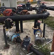
Booster pumps on a network of leachate force mains before connection to an off-site discharge line.
Inline and Offline Pumps
Booster pumps located along an expanded leachate force main can certainly be an option. Booster pumps can be the inline or offline type. Install the inline pumps on the actual force main, and position the offline type on the side so that liquids go through bends and elbows to reach the pump, and again through bends and elbows to get back in the force main. In either case, the booster pump adds hydraulic energy to the flow inside the force main to push the liquids at a compensated pressure through the remainder of the force main and to the target point.
Operators need to be aware of the dynamic nature of the leachate piping network and the role of booster pumps in the dynamic environment. Changes to the flow in the force main may change following a landfill expansion when the new cells are coming online increasing leachate generation. Alternatively, after closing portions of the landfill slopes, that decreases leachate generation over time. Sometimes booster pumps have to be up-sized or downsized depending on the flow and pressure in the system.
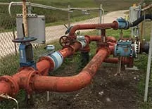
A junction of leachate force mains coming together from various operations.
Optimizing Performance, Reduce O&M Costs
The cost of replacing pumps, up-sizing, or downsizing, is insignificant compared to the revenue that landfills generate. Proper adjustment of the pumping system keeps the entire network operating at the appropriate range of pressure, and velocity in the line; increasing the life of the pumping system. Less wear and tear on the system produces a reduction in maintenance costs along with less equipment downtime.
Lower maintenance requirements may also reduce the number of personnel required to keep the system in operational condition. Landfills with a large pumping system employing a second technician because of the high maintenance of multiple pumps may find a single technician sufficient for the upkeep of the system. Proper sizing of pumps and operating the pumping system as designed within the evaluation parameters can significantly reduce the cost and frequency of pump maintenance.
About the Author: Ali Khatami, PhD, PE, LEP, CGC, is a Project Director and a Vice President of SCS Engineers. He is also our National Expert for Landfill Design and Construction Quality Assurance. He has nearly 40 years of research and professional experience in mechanical, structural, and civil engineering.
It is a general misconception that leachate seeps stop or disappear when slopes receive the final cover. In fact, it is only true if the source of leachate is located directly below the cover, but in most cases, the leachate originates from another location. Continuing seeps eventually reach the bottom of the slope, where two scenarios can happen depending on how the final cover geomembrane is secured at the landfill’s perimeter.
In the first scenario, where the geomembrane is anchored in an anchor trench, liquids will gradually flow underneath the cover geomembrane in the anchor trench and enter the perimeter berm structure. Leachate entering the berm structure softens the berm’s structural fill adversely impacting its shear strength. Additionally, leachate gradually seeps through the berm structure and enters natural formations below the berm and possibly into the groundwater. The operator is alerted when monitoring shows a localized structural failure or a groundwater impact in a nearby groundwater monitoring well.
In the second scenario, where the final cover geomembrane is welded to the bottom lining system geomembrane, leachate seeping out of the slope reaching the toe of the slope accumulates at the toe because it has nowhere to go. Accumulation of leachate behind the final cover geomembrane forces water to gradually move laterally along the landfill perimeter berm behind the final cover geomembrane damaging a larger area behind the final cover. Vertically, more of the area above the toe of the slope becomes engaged by the accumulating leachate. The two obvious consequences are the softening of the soil layer below the final cover geomembrane at the toe of the slope and the water-bedding effect of the area near the toe of the slope.
In the first scenario, the operator has to handle a non-compliance issue, either a failure in the slope or impacts to groundwater. In the second case, the leachate remains contained, but the operator has to address the issue by opening the final cover and removing leachate accumulated behind the final cover geomembrane. The geomembrane opening is closed, and final cover soils are restored after liquids are removed. Both are costly and complicated solutions. Moreover, the problem does not end after completion of the repair because the source of leachate seep is not eliminated.
Landfill operators can require their engineers to design a leachate toe drain system located at the toe of the slope and connected to the leachate collection system at the bottom of the landfill before the final cover geomembrane is installed. The leachate toe drain system is the only way to collect and route leachate to a location at the bottom of the landfill constructed for removal of leachate.
If you are closing a portion of your landfill slope and you find no leachate toe drain system in the construction plans, you can ask for a system to be added to the design plans before the commencement of the construction project.
SCS has significant experience with various types of leachate toe drain system constructed at different locations under various conditions. If you like to know more about the design of leachate toe drain systems or if you are looking for an experienced engineer for the design of your next final cover contact SCS.
Landfill base grades not only make leachate collection and removal possible but also have a significant impact on the amount of landfill airspace. For landfill operators, airspace is the primary asset, because it represents the level of revenue the operator can expect. Airspace is a commodity to be maximized.
Operators expect to get the most airspace from their landfill designer and depend on the engineer to design the grades to maximize it. Placing your trust in an engineer is a noble matter, but as the operator, you check, verify, and confirm that what the designer has engineered is what is needed to provide you with the expected value. An experienced landfill designer looks for ways to provide airspace above and beyond the operator’s expectations.
SCS has been in the business of designing landfills for nearly half a century. We have significant experience in optimizing landfill designs and maximizing airspace. SCS is often retained to design a new expansion to an existing landfill. Upon starting work we analyze the entire facility holistically to see all of the potential ways to maximize airspace around and above the existing landfill. Every cubic yard of additional airspace is a big achievement for our clients and in turn for us.
SCS often evaluates permitted, yet to be developed, base grades for operators. The intent is to determine whether additional airspace can be achieved by applying a different design to the base of the landfill. SCS has turned the science of geometry into mathematical models utilized to quickly evaluate base grades. Specific parameters of the currently permitted base grades are plugged in the mathematical model along with those of the alternative and the model provides quantitative values (cubic yards) of the difference between the permitted grades and the alternative. The values are quickly returned. After modeling, the operator may decide to modify the design to gain the additional airspace based on the alternative design. Contact us to work with our landfill design experts to assist you with an evaluation.
It’s been 10 years since the first Research, Development, and Demonstration (RD&D) Plans were approved allowing liquids to be applied to municipal solid waste landfills in Wisconsin. What have we learned?
Under an approved RD&D Plan, landfill operators can apply liquids other than recirculated leachate to the waste at municipal solid waste landfills. The RD&D Rule was published by US EPA in 2004, and states had the option of adopting the rule and issuing RD&D approvals. Wisconsin was an early adopter, and 13 of the approximately 30 landfill sites in the US with RD&D approvals are in Wisconsin.
This presentation will look at data from the Wisconsin landfills with RD&D Plans. Each site is required to report annually on a very detailed basis. For this presentation we will zoom out and look at the data on an aggregated basis to address big-picture questions. What are the trends in volumes applied for leachate recirculation versus RD&D Liquids? How do these volumes compare with precipitation? What liquid waste streams have been accepted and how have they been applied? How has RD&D liquid application affected landfill gas generation?
We will also provide an update on the regulatory status of the RD&D rule. On May 10, 2016, a final federal rule was published that revised the maximum permit term from 12 years to 21 years; however, WDNR will have to adopt this change in order for it to be available to Wisconsin landfills.
High-density polyethylene pipes have been used for landfill leachate collection and conveyance lines for several decades because of the chemical compatibility of HDPE material with many different types of liquids and chemicals. Designing a leachate collection system for a landfill disposal cell involves numerous engineering analyses of different components involved in collecting and conveying leachate. One of the important engineering evaluations is a determination of structural stability of HDPE leachate collection pipes at the bottom of the landfill.
Structural Stability of HDPE Pipe
Modern landfills are gradually becoming larger and deeper; deeper landfills will naturally impose a higher surcharge loading on the HDPE leachate collection pipes below the waste column. Engineering methodologies for the structural stability evaluation of HDPE pipes with significant surcharge loading have been around as long as HDPE pipes have been in production.
There are three criteria used when evaluating the structural stability of HDPE pipes; wall crushing, wall buckling, and ring deflection. Wall crushing can occur when the stress in the pipe wall, due to external vertical pressure, exceeds the compressive strength of the pipe material. Wall buckling, a longitudinal wrinkling in the pipe wall, can occur when the external vertical pressure exceeds the critical buckling pressure of the pipe. Ring deflection is the change in vertical diameter of the pipe as the pipe deforms under the external pressure. Empirical formulas by HDPE pipe manufacturers or researchers are available to check each criterion.
SDR 11 vs. SDR 17 HDPE Pipe
When a structural stability evaluation involves high surcharge loading on the pipe, an engineer may automatically select SDR 11 HDPE pipe without going through an evaluation process. The engineer’s reasoning is that the higher wall thickness of SDR 11 pipe, as compared to SDR 17 pipe, is the logical choice because it provides a higher level of structural stability to the pipe. In the case of wall bucking and wall crushing, where the pipe strength in these two criteria is inversely proportional to the SDR value, the engineer is making the right choice. The strength is greater for the lower SDR value that represents thicker pipe wall thickness; making SDR 11 stronger than SDR 17.
However, in the case of ring deflection, the pipe strength is not a function of SDR, but a function of another parameter called allowable ring deflection. The allowable ring deflection value varies from one SDR to another and is generally reported by pipe manufacturers. The allowable ring deflection for SDR 17 pipe is greater than all other SDR pipes, which makes SDR 17 pipe stronger when considering ring deflection. SDR 17 pipe is also the most commonly used HDPE pipe in the landfill industry, being lighter in weight per unit length of the pipe than SDR 11, thus making it less expensive than SDR 11 pipe.
Which Is Best For My Landfill?
SCS Engineers recommends that landfill engineers consider SDR 17 pipe as the first choice for use as a leachate collection pipe below the waste column, and then other SDRs if SDR 17 does not pass the three structural stability criteria mentioned above.
Read more blogs by Ali Khatami, click here and type “Advice from the Field” in the search box.
We continue SCS’s Advice from the Field blog series with guidance from an article in MSW Magazine by Daniel R. Cooper, Jason Timmons, and Stephanie Liptak.
Planning a landfill gas collection system before collection is required can increase the long-term benefits for multiple stakeholders.
The authors of a recent article in MSW Management Magazine present engineering ideas that provide for more efficient construction of a GCCS. Gas system operators will benefit by having fewer pumps to operate and maintain and shallower headers that are more easily accessible. Odor management will be easier along with other benefits.
Read the full article here to learn about the design elements for maximizing long-term benefits, impacting: bottom liners, location of the blower/flare station, leachate risers, extraction well targets, and external header piping.
 About the Author: Ali Khatami, Ph.D., PE, LEP, CGC, is a Project Director and a Vice President of SCS Engineers. He is also our National Expert for Landfill Design and Construction Quality Assurance. He has nearly 40 years of research and professional experience in mechanical, structural, and civil engineering.
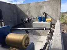
 About the Author: Ali Khatami, PhD, PE, LEP, CGC, is a Project Director and a Vice President of SCS Engineers. He is also our National Expert for Landfill Design and Construction Quality Assurance. He has nearly 40 years of research and professional experience in mechanical, structural, and civil engineering.